Image:Mutually inducting inductors.PNG
From Wikipedia, the free encyclopedia
No higher resolution available.
Mutually_inducting_inductors.PNG (231 × 174 pixels, file size: 3 KB, MIME type: image/png)
Summary
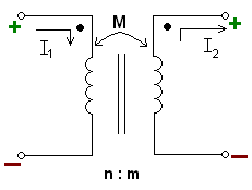
A picture of the usual depiction of mutual inductance. The two vertical lines between the inductors indicate a solid core that the wires of the inductor are wrapped around. "n:m" shows the ratio between the number of windings of the left inductor to windings of the right inductor. This picture also shows the dot convention.
Licensing
| |
I, the creator of this work, hereby grant the permission to copy, distribute and/or modify this document under the terms of the GNU Free Documentation License, Version 1.2 or any later version published by the Free Software Foundation; with no Invariant Sections, no Front-Cover Texts, and no Back-Cover Texts. Subject to disclaimers. |
File history
Click on a date/time to view the file as it appeared at that time.
| Date/Time | Dimensions | User | Comment | |
|---|---|---|---|---|
| current | 01:32, 19 October 2006 | 231×174 (3 KB) | Fresheneesz ( Talk | contribs) | (Fixing picture along with another. This has been wrong for months) |
| revert | 01:48, 15 April 2006 | 231×174 (3 KB) | Fresheneesz ( Talk | contribs) | (A picture of the usual depiction of mutual inductance. The two verticle lines between the inductors indicate a ''solid core'' that the wires of the inductor are wrapped around. "n:m" shows the ratio between the number of windings of the left inductor to w) |
See the setup instructions for more information.
File links
The following pages on Schools Wikipedia link to this image (list may be incomplete):
Categories: Self-published work