Capacitance
2008/9 Schools Wikipedia Selection. Related subjects: Electricity and Electronics
| Electromagnetism | ||||||||||||
 |
||||||||||||
Electricity · Magnetism
|
||||||||||||
Capacitance is a measure of the amount of electric charge stored (or separated) for a given electric potential.

In a capacitor, there are two conducting electrodes which are insulated from one another. The charge on the electrodes is +Q and -Q, and V represents the potential difference between the electrodes. The SI unit of capacitance is the farad; 1 farad = 1 coulomb per volt.
Capacitors
The capacitance of the majority of capacitors used in electronic circuits is several orders of magnitude smaller than the farad. The most common units of capacitance in use today are the millifarad (mF), microfarad (µF), the nanofarad (nF) and the picofarad (pF)
The capacitance can be calculated if the geometry of the conductors and the dielectric properties of the insulator between the conductors are known. For example, the capacitance of a parallel-plate capacitor constructed of two parallel plane electrodes of area A separated by a distance d is approximately equal to the following:

where
- C is the capacitance in farads, F
- ε is the permittivity of the insulator used (or ε0 for a vacuum)
- A is the area of each plane electrode, measured in square metres
- d is the separation between the electrodes, measured in metres
- ε is the permittivity of the insulator used (or ε0 for a vacuum)
The equation is a good approximation if d is small compared to the other dimensions of the electrodes.
The dielectric constant for a number of very useful dielectrics changes as a function of the applied electrical field, e.g. ferroelectric materials, so the capacitance for these devices is no longer purely a function of device geometry. If a capacitor is driven with a sinusoidal voltage, the dielectric constant, or more accurately referred to as the dielectric permittivity, is a function of frequency. A changing dielectric constant with frequency is referred to as a dielectric dispersion, and is governed by dielectric relaxation processes, such as Debye relaxation.
Energy
The energy (measured in joules) stored in a capacitor is equal to the work done to charge it. Consider a capacitance C, holding a charge +q on one plate and -q on the other. Moving a small element of charge dq from one plate to the other against the potential difference V = q/C requires the work dW:
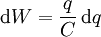
where
- W is the work measured in joules
- q is the charge measured in coulombs
- C is the capacitance, measured in farads
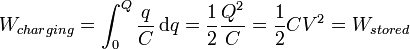
We can find the energy stored in a capacitance by integrating this equation. Starting with an uncharged capacitance (q=0) and moving charge from one plate to the other until the plates have charge +Q and -Q requires the work W:
Combining this with the above equation for the capacitance of a flat-plate capacitor, we get:
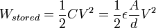 .
.
where
- W is the energy measured in joules
- C is the capacitance, measured in farads
- V is the voltage measured in volts
Capacitance and 'displacement current'
The physicist James Clerk Maxwell invented the concept of displacement current,  , to make Ampere's law consistent with conservation of charge in cases where charge is accumulating, for example in a capacitor. He interpreted this as a real motion of charges, even in vacuum, where he supposed that it corresponded to motion of dipole charges in the ether. Although this interpretation has been abandoned, Maxwell's correction to Ampere's law remains valid (a changing electric field produces a magnetic field).
Maxwell's equation combining Ampere's law with the displacement current concept is given as 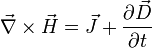 . (Integrating both sides, the integral of
  can be replaced — courtesy of Stokes's theorem — with the integral of
  over a closed contour, thus demonstrating the interconnection with Ampere's formulation.)
Capacitance/inductance duality
In mathematical terms, the ideal capacitance can be considered as an inverse of the ideal inductance, because the voltage-current equations of the two phenomena can be transformed into one another by exchanging the voltage and current terms.
Self-capacitance
In electrical circuits, the term capacitance is usually a shorthand for the mutual capacitance between two adjacent conductors, such as the two plates of a capacitor. There also exists a property called self-capacitance, which is the amount of electrical charge that must be added to an isolated conductor to raise its electrical potential by one volt. The reference point for this potential is a theoretical hollow conducting sphere, of infinite radius, centred on the conductor. Using this method, the self-capacitance of a conducting sphere of radius R is given by:

Typical values of self-capacitance are:
- for the top electrode of a van de Graaf generator, typically a sphere 20 cm in diameter: 20 pF
- the planet Earth: about 710 µF
Elastance
The inverse of capacitance is called elastance, and its unit is the reciprocal farad, also informally called the daraf.
Stray capacitance
Any two adjacent conductors can be considered as a capacitor, although the capacitance will be small unless the conductors are close together or long. This (unwanted) effect is termed "stray capacitance". Stray capacitance can allow signals to leak between otherwise isolated circuits (an effect called crosstalk), and it can be a limiting factor for proper functioning of circuits at high frequency.
Stray capacitance is often encountered in amplifier circuits in the form of "feedthrough" capacitance that interconnects the input and output nodes (both defined relative to a common ground). It is often convenient for analytical purposes to replace this capacitance with a combination of one input-to-ground capacitance and one output-to-ground capacitance. (The original configuration — including the input-to-output capacitance — is often referred to as a pi-configuration.) Miller's theorem can be used to effect this replacement. Miller's theorem states that, if the gain ratio of two nodes is 1:K, then an impedance of Z connecting the two nodes can be replaced with a Z/K impedance between the first node and ground and a KZ/(K-1) impedance between the second node and ground. (Since impedance varies inversely with capacitance, the internode capacitance, C, will be seen to have been replaced by a capacitance of KC from input to ground and a capacitance of (K-1)C/K from output to ground.) When the input-to-output gain is very large, the equivalent input-to-ground impedance is very small while the output-to-ground impedance is essentially equal to the original (input-to-output) impedance.